
Managing Flows in Smart Flows enables users to create, configure, and control the document generation process through the Project Console and Flow Builder. Users with the appropriate permissions can define flow logic, connect flow blocks using linked fields, and determine how outputs are structured and shared with downstream systems. Features such as Flow Output and linked fields provide flexibility for passing data between flow steps and external applications. Understanding these capabilities helps users build efficient, reusable, and well-structured automation workflows.
Creating a Flow
A flow is the logical sequence of steps a user defines to generate a document. Users can define and run their flows using the Smart Flows Project Console. To create flow, a user needs the security role of Administrator or Designer. This page describes the steps to create a flow in Project Console.
Steps for creating a flow
Note: You can also access the Flows section by clicking on the Flows tab in the Navigation Bar.
-
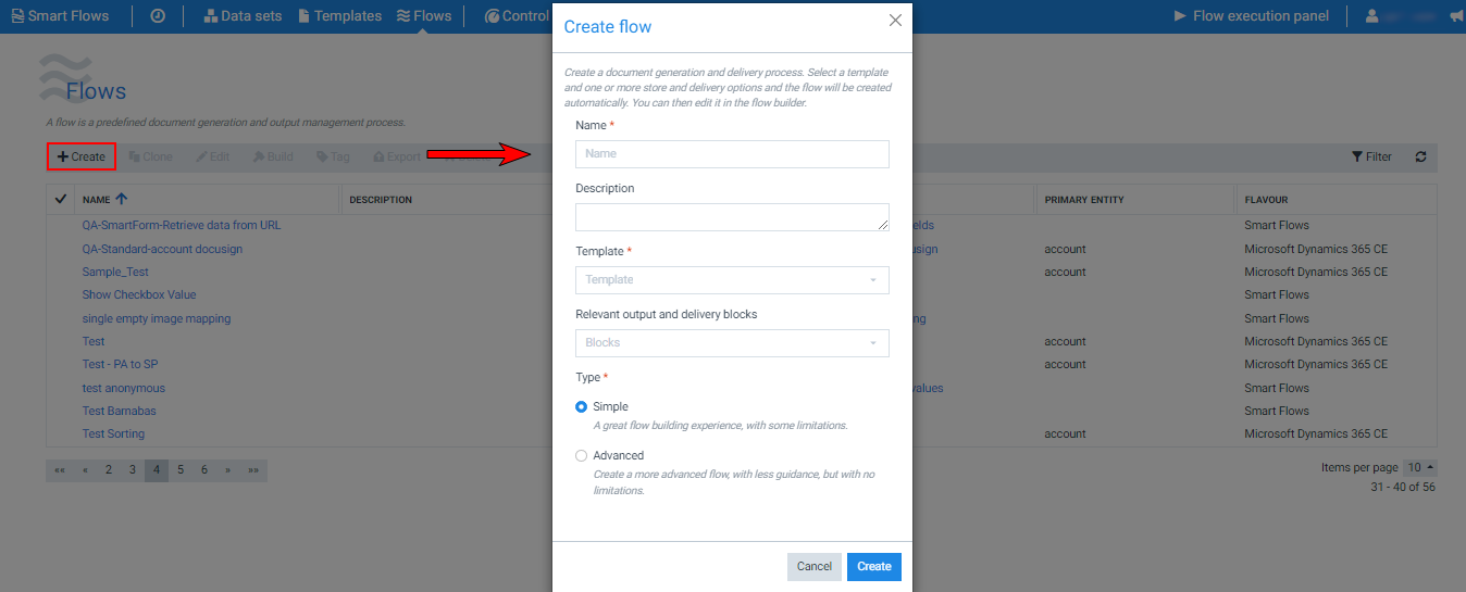
In Project Console, select Flows > Create.
-
In the Name field, input the name of the flow.
-
(Optional) In the Description field, input a description for the flow.
-
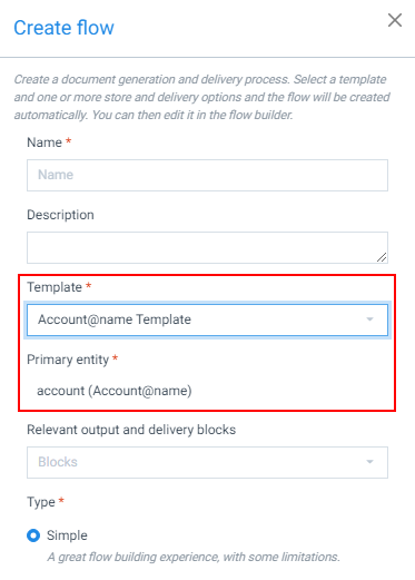
In the dropdown menu, select the Template you want to use for your flow.
The Primary entity field is auto-selected. The template uses a Primary entity to extract data from the data set.
Decision Point
The default in the Relevant output and Delivery blocks is Blocks. You can either select your desired output here or set this in the flow steps after creating a flow in the Flow Builder.
-
(Optional) From the dropdown menu, select the Relevant output steps.
Decision Point
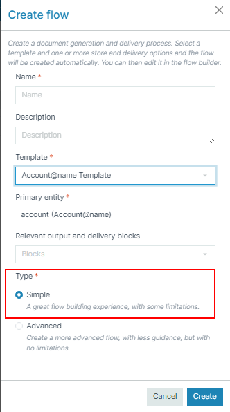
The Advanced type gives you more freedom to control each flow block. However, once a flow is set to Advanced, it cannot be reverted back to Simple.
-
Select the Type of flow. By default, the flow is set to Simple.
-
Select the Create button.
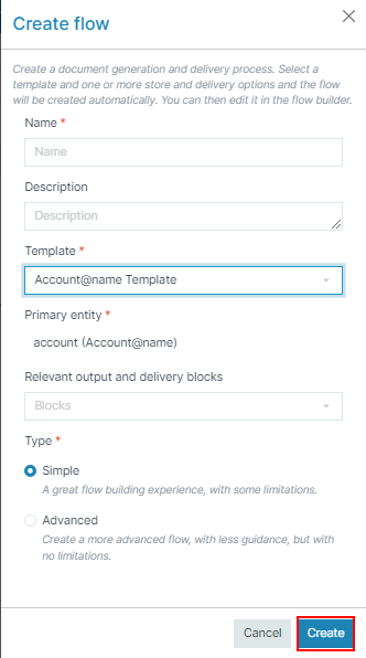
You are redirected to Flow Builder, which allows you to define the steps for your generated document.
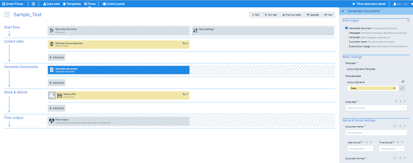
Linked Fields
Linked fields allow you to link a parameter field to another block's output or a data set field.
There are 3 reasons why you would want to link blocks together:
-
A block requires input, such as Print. If you don't give the Print block a Document as input, nothing will be printed.
-
You want to make a parameter field dynamic by using a data set field in it. For example, to personalize an e-mail, you put the AccountName field in the e-mail subject field.
-
You want to make a parameter field dynamic by using a block's output in it. Instead of selecting a data set field, it sometimes makes sense to use a block's output, such as Docusign's envelopeUri, which produces a link that you to the signed document. This could then be used in an email message text field to provide a link to signed document in the body of the email.
Visual cues
The flow builder comes with a few visual cues to help you identify linked blocks quickly.
-
Blocks linked to the selected block are gold-colored.
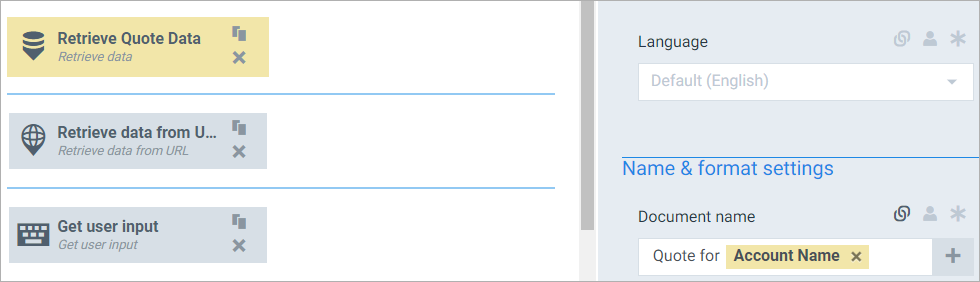
-
Hovering over a link in the flow block inspector colors both the link and the block that it points to in a darker gold.
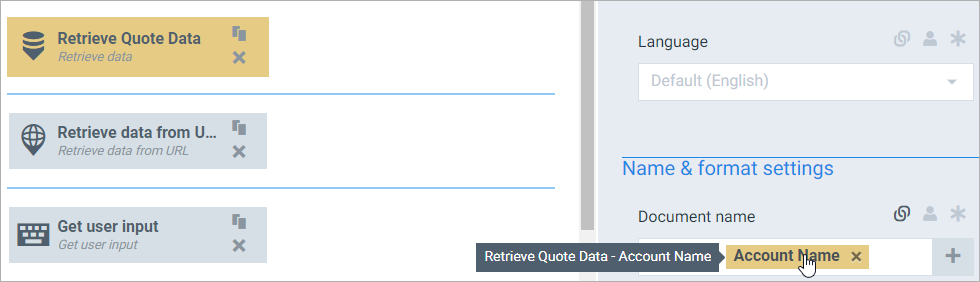
-
When hovering over a link in the flow block inspector, you can select Show full dependency chain to open an alternative view. In this view, blocks that are indirectly linked to the selected block (there is no direct link, but they are connected via blocks in between them) show a gold-colored highlight behind their icon. In the example pictured below, Create note is directly linked to Send to Docusign. It is also indirectly linked to the Generate Document and Create data.
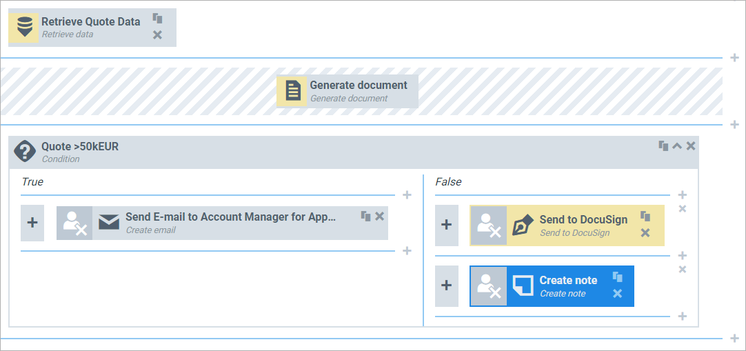
Procedures
Make a linked field
Not all parameter fields can be made into linked fields. Applicable fields will display the Linked field icon, allowing you to toggle between linked and normal behaviors.
-
Above the applicable parameter field, select the Linked field icon.

-
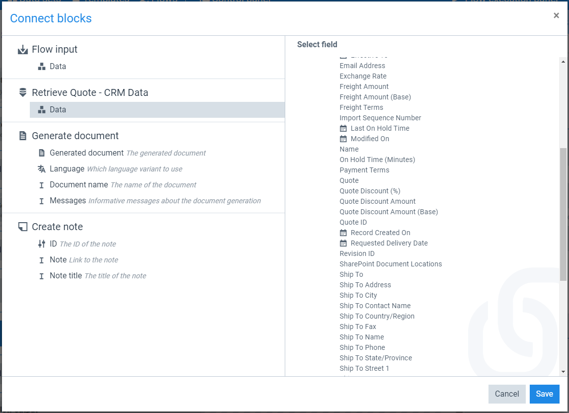
Select the + icon to open the Connect blocks modal.
-
In the left column, select the source of the data.
-
If you just need a block's output, you're done. If you require a data set field, you can then select it in the right column.
-
Select OK.
The selected output/field shows up in a gold-colored link in the linked field:
-
After clicking the icon, it turns bold, and a + symbol appears in the field. The parameter field is now a linked field, but there's no link in place yet.

Managing links in a linked field
Once a link is in place, you can add text or additional links to the linked field:

To edit a link, simply select it, and the Connect blocks modal opens.
Format date field
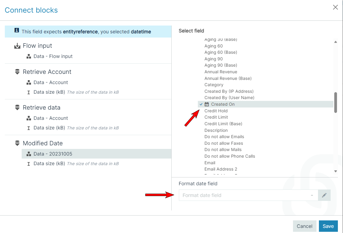
When configuring a linked field with a field of type 'Date', you'll notice a calendar icon next to the field. If you select the calendar icon, a field will appear at the bottom of the window, and you can specify the format you want Smart Flows to apply at execution time. You can select a predefined format from the drop-down or select the pencil icon to specify your own custom format.
Flow Output
The Flow Output step defines how data from a Smart Flow is structured and passed to downstream processes such as Dynamics workflows or external applications.
This topic explains how to structure flow output, configure output data instances, and map field values for reuse in subsequent systems.
Understand the Flow Output Block
Each Smart Flow ends with a Flow Output block. This block consolidates data produced during the flow execution and presents it to the end user or external process.
The Flow Output block performs two functions:
-
Displays the output from flow blocks to the user at runtime.
-
Enables mapping of values that can be reused in workflows or custom applications.
Configure Output Data
Use output data to transfer structured information from the flow to another system. Each instance of output data is based on a data set, which defines the format and available fields.
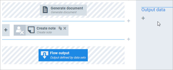
To define output data, select the + icon under the Output data section:
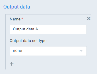
For each instance:
-
Enter a name for the output instance. This name is referenced in downstream systems.
-
Select a data set to structure the output. You can use an existing set or the pre-configured Dynamics workflows set if integrating with Microsoft Dynamics 365.
Map Fields to Output Data
Select Map fields to open the mapping dialog. This interface allows you to connect fields from flow blocks to fields in your selected data set:
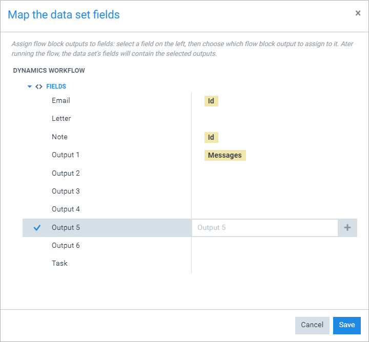
In the left column, the structure of the data set is shown. The right column displays mapped outputs from flow blocks.
Example: The ID of a created e-mail is mapped to the Email field, a note ID to Note, and document messages to Output 1. These values are then retrievable in a downstream process such as an automated document generation, see Generating Documents.
To map a value to a field:
-
Select a target field from the left column.
-
Select the + icon to open the block selector.
-
Choose a value from a flow block or enter static text.

Flow Output Panel
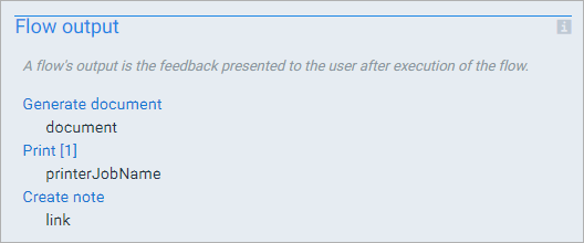
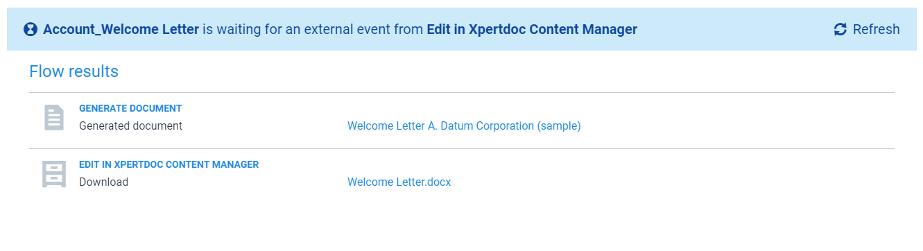
The Flow Output Panel allows users to view and interact with outputs generated by a completed flow or a flow that is paused while waiting for an external event. Most flow blocks can generate one or more output elements. For example, the Generate Document block may produce both a document and a document name as its output elements.
Flow Waiting for an External Event
The following image shows how the Flow Output Panel appears when a flow is waiting for an external event:
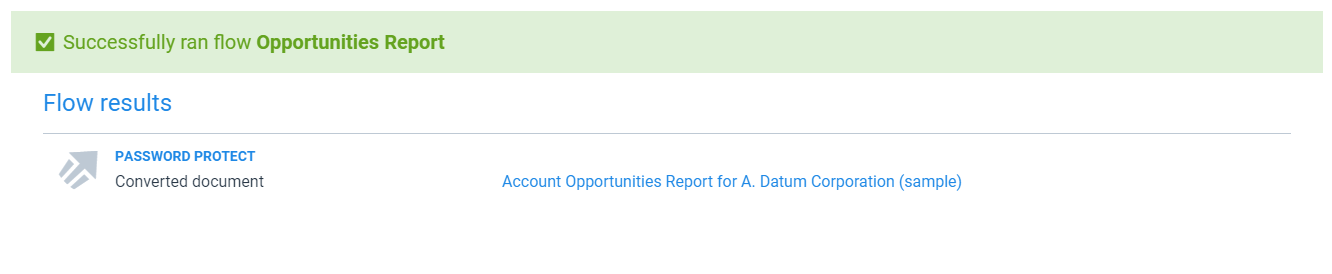
Completed Flow
After a flow has completed execution, the Flow Output Panel displays the results of the entire flow:
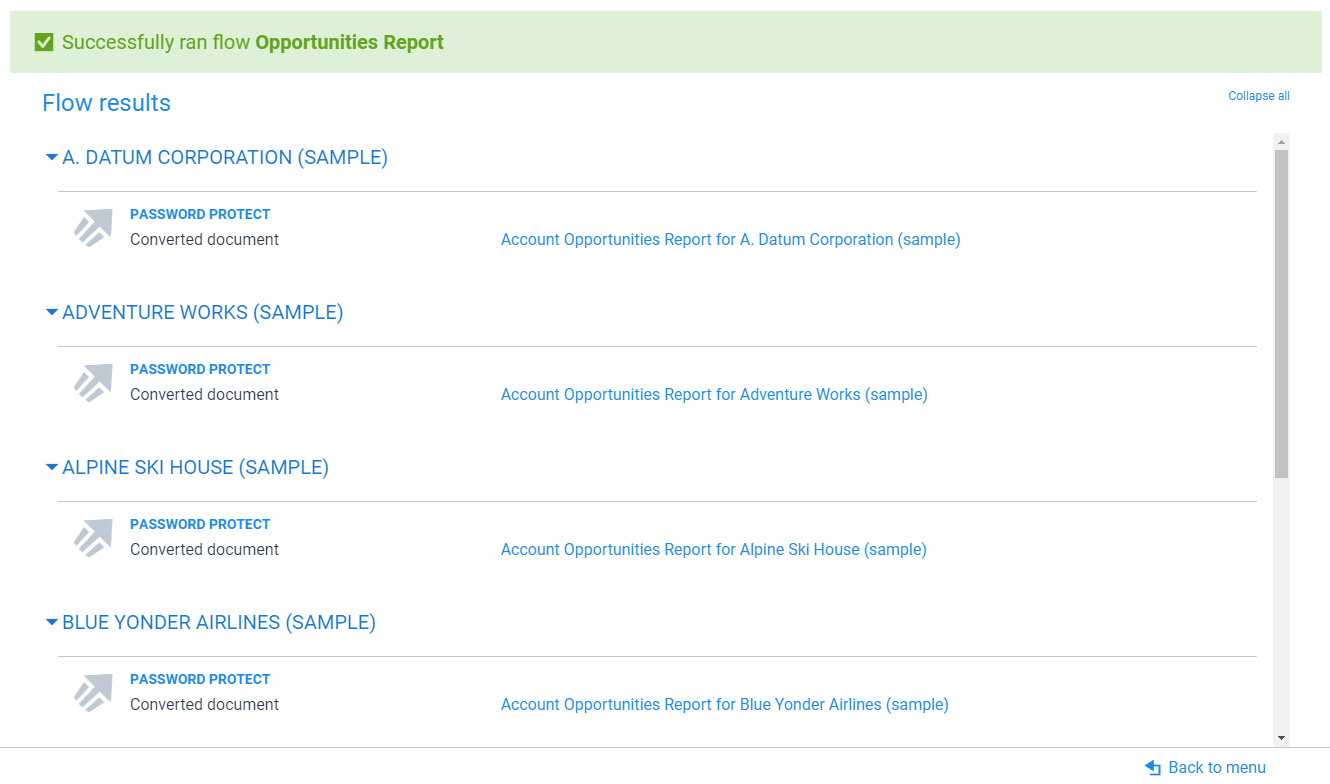
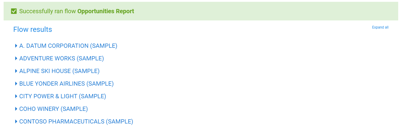
Multiple Records
When a flow is run on multiple records, each record’s output is grouped separately. Users can expand or collapse the display for individual records or for all records simultaneously.
|
Expanded View |
Collapsed View |
|---|---|
|
|